Sound sensitive lights w/ sound sensor & Arduino
Sound sensors can be used for a variety of things, one of them could be turning lights off and on by clapping. Today however we are going to use hook up the sound sensor to an array of LED lights which will beat with music, clapping or knocking.
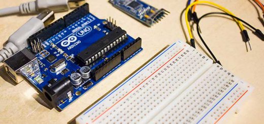
Requirements
- Almost any Arduino – I used the popular Arduino Uno
- Some breadboard cables
- A breadboard
- A sound sensor – I used a high sensitivity sound detection sensor module by Keyes
- At least 1 LED light – I used 7! The more the better!
- As many LEDs you are using you should have resistors. 333 ohm resistors should do the trick for most LEDs but I used 100 ohm ones.
Connecting the sound sensor
The sound sensor should look something like this.
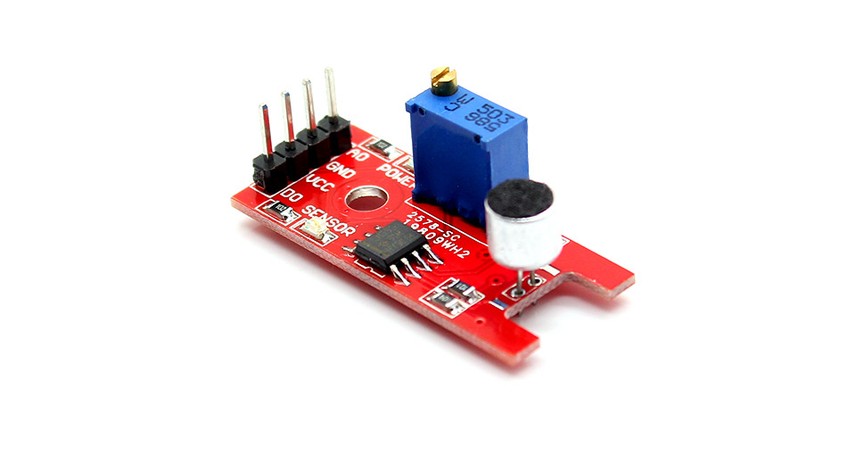
It has four pins that needs to be connected to your Arduino. The top one(if you look at the image above), is AO. This should be connected to the analog input 0 on the Arduino(A0). The one beside that is GND, which is connected to ground, the VCC is connected to +5V, and the last one is DO – which is the digital output of the module, and should be connected to digital pin 2 on the Arduino.
Here is the connection described with a table
[table width=”200″ align=”center”]Arduino Pin, Sound Sensor Pins
A0,AO
GND, GND
5V, VCC
Digital Pin 2, DO
[/table]
On the top of the sound sensor is a little flathead screw you can turn to adjust the sensitivity and analog output of the sound sensor. To calibrate the sound sensor you can run some music the background and keep turning it until you start seeing the sensor-LED on the module starts blinking with the rhythm.
Connecting the LEDs
Now if you are only going to use one LED, connect your resistor from ground to the shorter side of the LED, and the long side of the LED to digital pin 3 on the Arduino.
If you have even more LEDs, keep doing the same but connect the next one to digital pin 4, the next one to digital pin 5 etc. I’ve written code to support 7 LED lights, which means you use digital pin 3 all the way to 9 for your LEDs. The reason I just didn’t connect the LEDs in parallel and then to only one digital pin, is because on for instance the Uno’s digital pins doesn’t have enough juice to fully power all those power hungry LEDs. You could use a transistor or a 7HC595N, but I just wanted to do a simple sound sensor tutorial so I didn’t include any of that in this post.
So basically Arduino Digital Pin(3-9) –> Positive Side of LED –> Negative Side of LED –> 333 ohm resistor –> Arduino Ground Pin(GND)
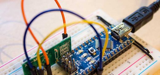
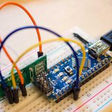
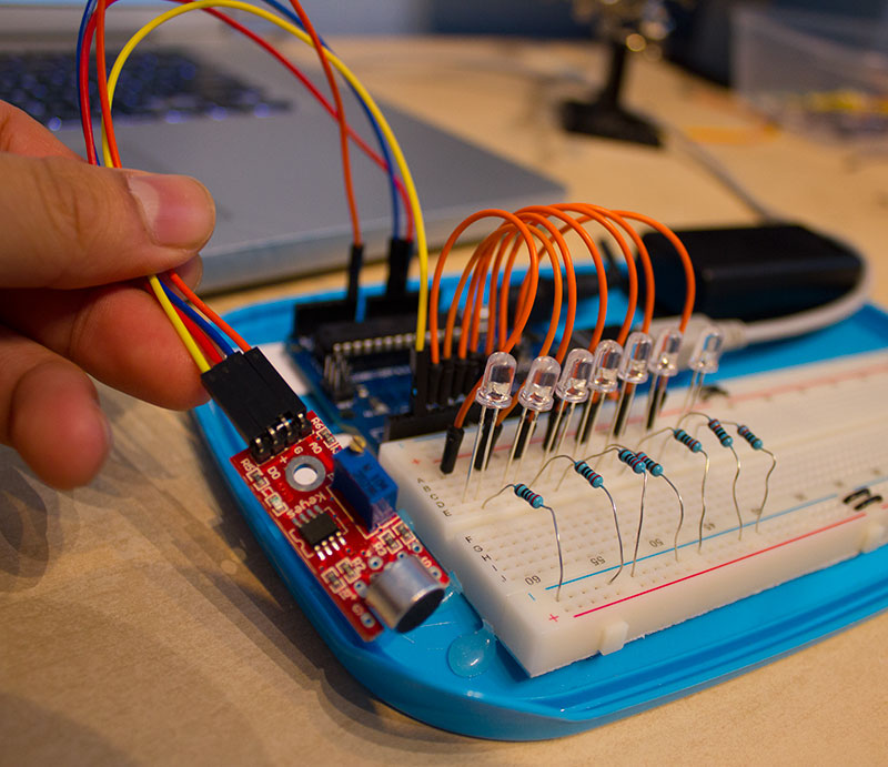
When its all connected it should look something like this
Programming the Arduino
Below is the Arduino code. I don’t count on it to work instantly after uploading the code to your Arduino. It needs some calibration first. But first, copy the code to the Arduino software.
int DO = 2; //Pin for Digital Output - DO
int DA = A0; // Pin for Analog Output - AO
int threshold = 532; //Set minimum threshold for LED lit
int sensorvalue = 0;

void setup() {
  //Serial.begin(9600);
  pinMode(3, OUTPUT);
  pinMode(4, OUTPUT);
  pinMode(5, OUTPUT);
  pinMode(6, OUTPUT);
  pinMode(7, OUTPUT);
  pinMode(8, OUTPUT);
  pinMode(9, OUTPUT);
}

void loop() {
  sensorvalue = analogRead(DA);  //Read the analog value
  //Serial.print("Analog: ");
  //Serial.print(sensorvalue);  //Print the analog value
  //Serial.print("  ");
  //Serial.print("Digital: ");
  //Serial.println(digitalRead(DO));  //Print the digital value

  if (sensorvalue >= threshold) { //Compare analog value with threshold
    digitalWrite(3, HIGH);
    digitalWrite(4, HIGH);
    digitalWrite(5, HIGH);
    digitalWrite(6, HIGH);
    digitalWrite(7, HIGH);
    digitalWrite(8, HIGH);
    digitalWrite(9, HIGH);

  }
  else {
    digitalWrite(3, LOW);
    digitalWrite(4, LOW);
    digitalWrite(5, LOW);
    digitalWrite(6, LOW);
    digitalWrite(7, LOW);
    digitalWrite(8, LOW);
    digitalWrite(9, LOW);
  }
}
Now remove the all the comment-slashes which has ‘Serial’ commented out, for instance “Serial.begin(9600)” and “Serial.print(“Analog: “);”. When you did that upload the code to your Arduino. This will enable serial output which you can view by using the Serial Monitor from the Arduino software. You can open the Serial Monitor by going to Tools > Serial Monitor or pressing the magnifying glass-button in the Arduino software window. What prints out is the analog and digital values of from the sound sensor module. The analog value should spike up when a noise occurs and stabilize when it gets quiet again. Now in the code there is an “int threshold = 532;” line that needs to be changed to something very close but higher than the value you get from the Serial Monitor when it is quiet around you. For instance if you see an analog value of 253, then threshold should be changed to perhaps 255 or 257. When a sound occurs, the analog value will rise and go above the threshold value. When that happens your LEDs will turn on. When it gets quiet again the analog value will go back to 253 and the LEDs go dark again. When you think the calibration is finished, recomment the Serial-commands and reupload the code to your Arduino. Commenting out any Serial-commands is important due to the Serial commands take very much processing power from the Arduinos, and will affect the performance of the sound sensor and blinking.
You should now be finished!
Start some music and see the awesome lights blink with the beat of the sound!
If you have any questions feel free to ask me by using the Contact page or by commenting below.