Basic LED blinking w/ Raspberry Pi
Now I’m not going to show how to setup Raspbian or SSH with your Pi. There are tons of tutorials online how to do that. I will however guide you through to setting up the necessary software for Raspbian to be able to control the pins on the Raspberry Pi.
Requirements
- Working Raspbian OS
- SSH connection or keyboard and display hooked up to Raspberry Pi
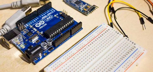
- Two breadboard jumper wires female to male
- 330 Ω resistor
- LED
Connecting the components
Now, the pins on the Raspberry Pi are usually called the GPIO pins, which is short for General-Purpose Input/Output. This is explained so you don’t get confused whenever you hear “gpio” in the forums. These pins are layed out with in two headers if you have the Mod B rev. 2 version. If you have another version you should only have one header. These two headers are called P1 and P5. The P5 is the header only available on the Mod B rev.2, and it’s purpose is to give the possibility to connect from under the Raspberry Pi. P1 is the header we will be using and is available throughout the different Pi models.
Observe! This pin layout is for the Raspberry Pi Mod B rev. 2!. Make sure you have this model before using the below layout as cheat sheet!

Raspberry Pi Mod B rev. 2 pin layout
Connect the first female-male wire from the GPIO 17 to the resistor, the resistor should connect the the anode of the LED. The LED’s cathode should connect to the second wire and the wire should then connect to one of the GND-pins
So GPIO 17 –> wire –> resistor –> LED’s anode –> LED’s cathode –> wire –> GND pin
Installing the required software
Next is to get the software ready. There are several ways to control the GPIO pins with software. The easiest way is to use GPIO-utility which is supplied by WiringPi.
To install WiringPi run these commands:
git clone git://git.drogon.net/wiringPi
cd wiringPi
cd wiringPi
./build
Turning the LED on and off
When the installation is done you can now use the GPIO-utility by running
gpio -g mode 17 out
The code about sets the GPIO 17 pin as output for +3.3V.
To turn on the LED run this code:
gpio -g write 17 1
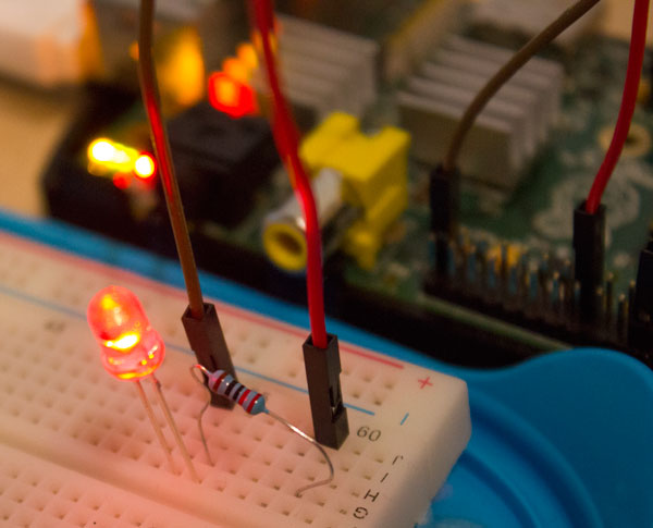
Here’s how it looks on my end:

LED in the HIGH state
To turn the LED off again run
gpio -g write 17 0
If you have any questions feel free to ask me by using the Contact page or the comments below.