Electronic dice w/ tilt sensor, 7 segment display and Arduino
For fun I made a dice using Arduino, tilt sensor and a 7 segment display.
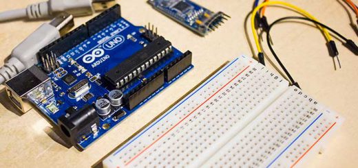
Hardware requirements
- Arduino(I used an Arduino Uno)
- Tilt sensor(a button could be used, if you’d like to press instead of shake)
- 7 segment display(with a dot)
- 10 K ohm resistor
- A breadboard
- Some jumper wires
Connecting the 7 segment display
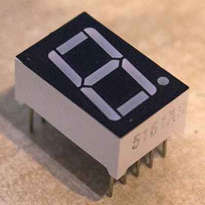
First we’ll connect the display and make sure it works. Here is the data sheet to a pretty common 7 segment display that I used in this project.
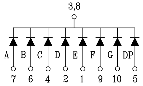
Picture nr 1
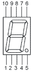
Picture nr 2
Picture nr 3
“Picture nr 1” shows the segment labels, the “Picture nr 2” shows what the pin numbers are, and the last one(picture nr 3) shows that pin 3 and 8 are to be connected to ground, and all the other pins turn on a segment on the display when connect to a power source.
This is how you connect the display to the Arduino. The table below was taken from this post.
[table width=”200″ align=”center”]Arduino Digital Pin, 7 Segment display pin connection
2,7 (A)
3,6 (B)
4,4 (C)
5,2 (D)
6,1 (E)
7,9 (F)
8,10 (G)
9,5 (DP)
GND,3
GND,8
[/table]
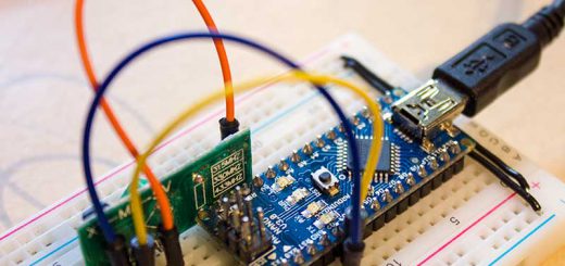
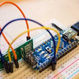
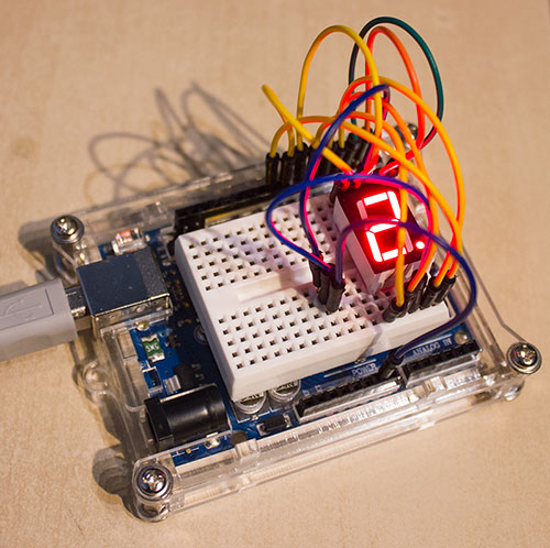
And this is how it looks on my end
Testing the display
Upload the code to your Arduino and the display should start counting down from 9. When it hits 0 it resets after a while and starts counting down again from 9. This code was taken from a tutorial on how to use a 7 segment display, link to the post is here. The code should not be credited to me.
// Arduino 7 segment display example software
// http://www.hacktronics.com/Tutorials/arduino-and-7-segment-led.html
// License: http://www.opensource.org/licenses/mit-license.php (Go crazy)

// Define the LED digit patters, from 0 - 9
// Note that these patterns are for common cathode displays
// For common anode displays, change the 1's to 0's and 0's to 1's
// 1 = LED on, 0 = LED off, in this order:
//                                    Arduino pin: 2,3,4,5,6,7,8
byte seven_seg_digits[10][7] = {
  { 1, 1, 1, 1, 1, 1, 0 }, // = 0
  { 0, 1, 1, 0, 0, 0, 0 }, // = 1
  { 1, 1, 0, 1, 1, 0, 1 }, // = 2
  { 1, 1, 1, 1, 0, 0, 1 }, // = 3
  { 0, 1, 1, 0, 0, 1, 1 }, // = 4
  { 1, 0, 1, 1, 0, 1, 1 }, // = 5
  { 1, 0, 1, 1, 1, 1, 1 }, // = 6
  { 1, 1, 1, 0, 0, 0, 0 }, // = 7
  { 1, 1, 1, 1, 1, 1, 1 }, // = 8
  { 1, 1, 1, 0, 0, 1, 1 } // = 9
};

void setup() {
  pinMode(2, OUTPUT);
  pinMode(3, OUTPUT);
  pinMode(4, OUTPUT);
  pinMode(5, OUTPUT);
  pinMode(6, OUTPUT);
  pinMode(7, OUTPUT);
  pinMode(8, OUTPUT);
  pinMode(9, OUTPUT);
  writeDot(1);  // start with the "dot" on
}

void writeDot(byte dot) {
  digitalWrite(9, dot);
}

void sevenSegWrite(byte digit) {
  byte pin = 2;
  for (byte segCount = 0; segCount < 7; ++segCount) {
    digitalWrite(pin, seven_seg_digits[digit][segCount]);
    ++pin;
  }
}

void loop() {
  for (byte count = 10; count > 0; --count) {
    delay(1000);
    sevenSegWrite(count - 1);
  }
  delay(4000);
}
If the numbers are weird looking then you probably didn’t connect the display right. Recheck you connected the right pins on the display to the right pin slots on the Arduino
Connecting the tilt sensor
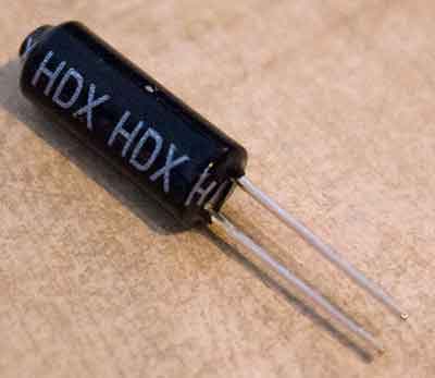
The tilt sensor is basically a simple switch. The switch is open when it’s pointing up, and is closed when up-side-down. It has two pins, and just like a switch, doesn’t matter what way the current is flowing.
Connect one side of the tilt sensor to Arduino digital pin 12 and the other side to the 5 volt pin.
So the circuit should be Arduino digital pin 12 –> Tilt Sensor –> 5 volt pin
Before we upload the final code we need to do one more thing. We need to connect a pull-up resistor. Get a 10K ohm resistor and connect it to the wire coming from Arduino digital pin 12. and the other side of the resistor to an empty row om the breadboard. Then run a cable from the other side of the resistor to the ground pin on the Arduino.
So the circuit should be Arduino digital pin 12 –> resistor –> Arduino ground(GND) pin
Now hardware should all be setup, time to upload the final code
Uploading the Arduino code
The code below is a modified version of the code I got from this site. I modified it to wait for the tilt sensor to close before looping through a set of random numbers between 1 to 6 and then freezing on the last one. Also as a detail I made the dot on the display light up when “shaking” the dice.
// Define the LED digit patters, from 0 - 9
// Note that these patterns are for common cathode displays
// For common anode displays, change the 1's to 0's and 0's to 1's
// 1 = LED on, 0 = LED off, in this order:
//                                    Arduino pin: 2,3,4,5,6,7,8
byte seven_seg_digits[10][7] = {
  { 1, 1, 1, 1, 1, 1, 0 }, // = 0
  { 0, 1, 1, 0, 0, 0, 0 }, // = 1
  { 1, 1, 0, 1, 1, 0, 1 }, // = 2
  { 1, 1, 1, 1, 0, 0, 1 }, // = 3
  { 0, 1, 1, 0, 0, 1, 1 }, // = 4
  { 1, 0, 1, 1, 0, 1, 1 }, // = 5
  { 1, 0, 1, 1, 1, 1, 1 }, // = 6
  { 1, 1, 1, 0, 0, 0, 0 }, // = 7
  { 1, 1, 1, 1, 1, 1, 1 }, // = 8
  { 1, 1, 1, 0, 0, 1, 1 } // = 9
};

const int tiltSensorPin = 12; // the number of the tilt Sensor pin
int tiltSensorState = 0;
int count = 0;

void setup() {
  pinMode(2, OUTPUT);
  pinMode(3, OUTPUT);
  pinMode(4, OUTPUT);
  pinMode(5, OUTPUT);
  pinMode(6, OUTPUT);
  pinMode(7, OUTPUT);
  pinMode(8, OUTPUT);
  pinMode(9, OUTPUT);
  writeDot(0);  // start with the "dot" off
  pinMode(tiltSensorPin, INPUT);
}

void writeDot(byte dot) {
  digitalWrite(9, dot);
}

void sevenSegWrite(byte digit) {
  byte pin = 2;
  for (byte segCount = 0; segCount < 7; ++segCount) {
    digitalWrite(pin, seven_seg_digits[digit][segCount]);
    ++pin;
  }
}

void throwDice() {
  writeDot(1);
  for (byte count = 30; count > 0; --count) {
    delay(40);
    sevenSegWrite(random(1, 6));
  }
  writeDot(0);
}

void loop() {
  tiltSensorState = digitalRead(tiltSensorPin);
  if (tiltSensorState == LOW) {
    count++;
    delay(10);
  }
  if (count == 20) {
    throwDice();
    count = 0;
  }
}
Now just aggressively shake the tilt sensor and watch the pretty display randomly choose a number!
If you have any questions feel free to ask me by using the Contact page or by commenting below.